Software
General architecture
The software consists of several cooperating components - they are divided into individual directories:
App/Server - server (management) application, run on a managing/calculating machine, PC: Windows 10 or Linux
Client - client applications (physically controlling the hardware), run on a machine physically connected to the servo and camera: Raspberry, Arduino or PC: Windows 10 or Linux
Web - web application, i.e. a separate version of the application, which can be run under a web browser, allowing you to control servos using a browser on a computer or smartphone.
The server application and the web application can operate simultaneously as a server + client (i.e. it is possible to connect the hardware directly to them via a USB port - then a separate client application is not required and the whole thing can be controlled locally directly from the server application).
In the case of web applications, it is required to run a web server. A production webserver, e.g. Nginx is recommended due to greater efficiency and reliability, but it is also possible to run the whole thing using a simple webserver for Python built-in (Flask) framework, included in the package.
Server applications have been prepared for two operating systems: Windows 10 and Linux - they are portable, i.e. they do not require any installation in the system, just unpack the archive - all libraries required for work are contained locally in their directories. The desktop application code was written in Python v3.10, PyInstaller was used to prepare binary/executable versions for Windows and Linux.
App/Server - server application (Windows, Linux)
The desktop server application that manages the whole thing is designed to run on the user’s computer, which will control the operation of the mechanism. It is located in the App (Server) directory and is available for Windows and Linux.
In the local operating mode, the Application allows for connection of all accessories (USB camera and microcontroller in the form of e.g. Arduino or Raspberry to control servos) directly to the computer on which the application is running. In the second mode - remote operation, it allows you to manage the equipment connected to the remote device (the so-called client, e.g. a Raspberry minicomputer with a client application running and a CSI camera and a controller for servos connected), communication then takes place via the network/WiFi.
Camera and servo connection options
Local Mode - CAM (USB)
In this mode, both the camera and the microcontroller (e.g. Arduino) or Raspberry computer are connected directly via USB ports to the same machine on which the server application is running.
As the operating mode, select the CAM (USB) in order to get an video capture from the camera connected directly to the USB port. In the Servo menu select the Local > (serial port) option from the list, where (serial port) is the name under which it is available, e.g. Arduino with servos connected. The port name may vary depending on the operating system and devices already connected, e.g. COM5 on Windows and /dev/ttyACM0 or /dev/ttyUSB0 on Linux.
In this operating mode, the server application here behaves simultaneously as a client and server, working with locally connected hardware.
Remote Mode - CAM (IP)
In the CAM (IP) remote operation mode, the server connects to the remote client application (running e.g. on a Raspberry minicomputer or any other computer connected via the network/WiFi) and remotely receives only the video capture from the camera from the client application, and then performs all calculations and controlling the whole by remotely sending control commands to the client (who then sends them further to the servo).
To connect to a remote client application, select CAM (IP) mode, and then enter the host name or IP address under which the client machine is available in the network. Then select the Connect / activate option from the context menu available with the right mouse button (PPM) on the list of connected clients located on the left side of the main program window in the IP tab.
NOTE: the connection to the client can sometimes be lost for various reasons, e.g. due to a physical power failure of the remote machine. The application then automatically attempts to resume such connections in order to restore communication, but if this fails, then to restore the connection manually, you must reconnect to the client (again selecting the Connect / activate option). In the context menu on the list of clients, there are also options such as Restart, which restarts the connection on the client’s machine, and the Destroy option, which shuts down the client application remotely and restarts it if a Supervisor type application is installed on the client. This may be useful, for example, in the event of any problems with the operation of the client application on the client’s computer.
When working with a remote client, only one client is active on the screen at a time, however video data is received all the time from all connected clients simultaneously. This can be used by selecting the Preview tab , which will show in one window a summary image from all simultaneously connected clients.
The list of clients, which will be loaded automatically into the application at the time of its launch, can be prepared manually by editing the hosts.txt file located in the directory with the server application and copied to the user’s directory during the first launch. In this file, the names of client computers should be given, each in a separate line and according to the scheme host [space] IP [space] description , as shown below:
hostname1 ip1 name1
hostname2 ip2 name2
hostname3 ip3 name3
Sample hosts.txt file:
raspberry1 192.168.0.2 kitchen
raspberry2 192.168.0.3 lobby
The hosts (clients) from this file are loaded into the program automatically when it is launched.
Thanks to this, you can prepare a list of your own devices, which will be loaded automatically and will significantly speed up clients management. The hosts file can also be edited directly from the server application: Menu > Configuration > Edit hosts.txt.
Remote mode - STREAM (webserver, HTTP / MJPEG)
STREAM remote mode the server connects to the webserver run by the remote client application (running e.g. on a Raspberry minicomputer or any other computer connected via the network/WiFi) and downloads only the camera image from the webserver, and then takes care of all calculations and control of the whole by sending remote control commands to client via HTTP (the client then forwards the commands to the servo).
To connect to a remote web server, select the STREAM mode, and then enter the host name or IP address and port under which the client machine is available in the network. Then select the Connect / activate option from the context menu available with the right mouse button (PPM) on the list of addresses with stream located on the left side of the main program window in the STREAM tab.
When working with a remote web server, only one client is active on the screen at a time.
streams.txt is a file located in the directory with the server application and copied to the user’s directory during the first launch. In this file, the names of client computers should be given, each in a separate line and according to the scheme protocol://host:port [space] description, as shown below:
protocol1://hostname1:port1 name1
protocol2://hostname2:port2 name2
protocol3://hostname3:port3 name3
Sample streams.txt file:
http://192.168.0.2:8888 kuchnia
http://192.168.0.3:8888 korytarz
Stream addresses from this file are loaded into the program automatically when it is launched.
If a security token is used for the connection, it should be added to the entry after the pass= prefix.
Example:
http://192.168.0.2:8888 kitchen pass=12345
Thanks to this, you can prepare a list of your own devices, which will be loaded automatically and will significantly speed up host management. The streams file can also be edited directly from the server application: Menu > Configuration > Edit streams.txt.
To be able to connect via the webserver, the client must be started with the ``web=1`` option:
python ./client.py --web=1
Note: the web connection is slower than the IP connection (via sockets) - there may be delays in video transmission when simultaneously sending control commands and during the entire working time, the video may be delayed by approx. 500ms in relation to the video sent using the socket method.
Modes of work with different video sources
The server application can work with 4 different video sources:
CAM (USB) - control of a camera connected locally to the USB port, and servos locally connected via the USB port, e.g. using Arduino
CAM (IP) - remote control via sockets of the camera and servomotors connected via the network, e.g. to Raspberry Pi or to another remote computer
VIDEO - the ability to run a video file instead of the video from the camera
STREAM - the ability to receive a stream (IPTV) or connect and control servers via a webserver built into the client
CAM (USB)
In this mode, connect the camera to the USB port of the computer on which the server application is running. The servos should be connected to the Arduino or Raspberry, and the Arduino or Raspberry should be connected to the same computer via the USB port and then select this port in the application in the Servo > Local > (port name) menu.
Note: the port must be available to the application, using it at the same time by another application will block its use here. If the system lacks drivers, e.g. for Arduino, you must first install the appropriate drivers provided by the manufacturer.
CAM (IP)
In this mode, the server application connects remotely (via the network / WiFi) with an external computer (client) to which the camera and servos are connected. Communication then takes place using the TCP protocol, the image from the camera is then sent remotely from the client to the server, and control commands are sent from the server to the client via a network socket (socket).
The role of the client to which the camera and servos can be remotely connected can be any computer, e.g. a regular desktop, mini-desktop or Raspberry. The only requirement is that it should be available via the network/WiFi and that it should provide physical communication (control) with servos, e.g. using an Arduino connected to the USB port, or directly through its GPIO PWM pins (if the customer is e.g. Raspberry).
Connecting to clients (IP)
To connect to a remote client, the client application (from the Client directory) must be running on it.
Then, using the server application, enter the client’s IP address under which it is available in the network in the address bar at the top of the window:

After entering the address and clicking the Connect button, an attempt will be made to connect to the client, and the client should appear on the list of clients on the left side of the program window:
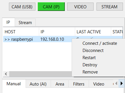
In case of connection problems, make sure that the client application is running on the client machine and that the host/IP addresses are correct. In case of problems, you can also use the Restart or Destroy options available from the context menu (RMB) in the list of clients.
The list of clients loaded when starting the server application can be edited in the hosts.txt file located in the directory with the server application.
At a given moment, one client can be managed from the level of the server application, however, the connection is maintained with all connected clients, therefore, using the Preview tab, you can view the current preview from all simultaneously connected clients and e.g. switch to the appropriate client using the list of clients by selecting the option Connect / Activate.
Tip: On the client’s computer, along with the client application, software for managing processes in the system should also be installed, e.g. Supervisor, which can automatically restart the finished application in the event of problems. The client application should also be loaded into memory with the system startup (autostart), if it is running on, for example, a Raspberry.
The Supervisor application can be downloaded from the manufacturer’s website: http://supervisord.org/
VIDEO
In this mode, you can load any video file (e.g. mp4) from the disk or URL, and then run the tracking mode on it. The mode can be useful, for example, for testing purposes, to test the behavior on video material.
STREAM
In this mode, you can load a remote stream from a URL, e.g. from IPTV, by specifying the address to the m3u8 file.
This allows you to connect an image from an external stream.
In this mode, you can also connect to a client working in web mode (with a running webserver). Such a connection can be more stable than a socket / IP connection (the webserver is running all the time, there is no need to establish a permanent connection between sockets), but the image can be sent with a greater delay. Support for the stream mode is similar to the CAM (IP) mode, with the difference that the connection goes through the web server built into the client. Using this mode, you can remotely control the server - commands are sent to the webserver and interpreted by the webserver.
Control modes
The control of the whole is divided into 2 main modes: manual and automatic.
In the left part of the window there are tabs for selecting the appropriate mode and additional tools.
Tabs description:
Manual - allows you to remotely control the mechanism using buttons and mouse, zoom, and manually turn on/off the action
Auto (AI) - allows you to automatically control the mechanism using built-in artificial intelligence (AI) models
Area - allows you to limit the working modes for AI by setting the allowed area on the screen
Filters - allows you to filter object types, e.g. specifying classes for detected objects or their minimum scoring
Video - allows you to control the video image
Options – allows live configuration of the basic parameters of the tracking mode and servo operation (these and all other parameters are configurable in the config.ini file)
Manual mode
In this mode, you can control the entire mechanism manually.
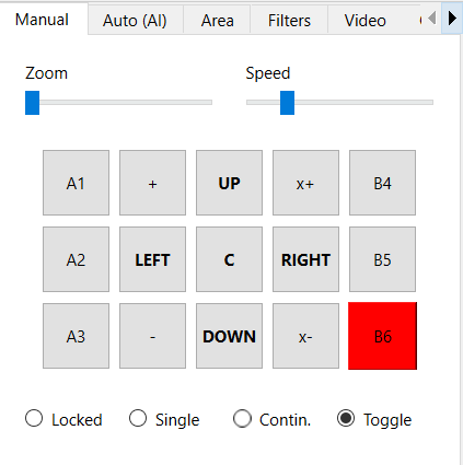
Using the mouse (with the left button pressed - LMB), you can move the mechanism by moving the mouse around the area with the image from the camera. You can also use the UP, DOWN, CENTER, LEFT, RIGHT buttons on the left side to control. Use the Speed slider to change the speed of the mechanism in manual mode. With the Zoom slider you can zoom in or out the image from the camera (digital zoom).

On the sides of the control buttons there are buttons with actions ( A1, A2, A3, B4, B5, B6).
Actions (manual and automatic)
The system allows you to remotely trigger predefined actions (remote control of additional behaviors on a connected device). There are 6 different slots for 6 different actions: A1-A3 and B4-B6. These slots allow you to remotely activate a given action, where, for example, action A1 can be responsible for giving +5V (HIGH state) on a defined pin on Arduino or Raspberry, and action B4 for giving +5V on yet another pin. The code for Arduino available in the Client / Arduino directory defines the default pins for individual actions and the code that activates them - on the Arduino side, all you need to do is connect the appropriate devices to the appropriate pins:
#define PIN_SERVO_X 10 // servo X (horizontal) PWM pin
#define PIN_SERVO_Y 11 // servo Y (vertical) PWM pin
#define PIN_ACTION_1 2 // action #1 (A1) DIGITAL pin
#define PIN_ACTION_2 4 // action #2 (A2) DIGITAL pin
#define PIN_ACTION_3 7 // action #3 (A3) DIGITAL pin
#define PIN_ACTION_4 8 // action #4 (B4) DIGITAL pin
#define PIN_ACTION_5 12 // action #5 (B5) DIGITAL pin
#define PIN_ACTION_6 13 // action #6 (B6) DIGITAL pin
With the above code uploaded to the Arduino, activating the A1 action will set pin 2 in HIGH state, and disabling the A1 action will set the pin to LOW state. Similarly, it happens for other actions and other pins defined for them. The configuration of the GPIO pins for Raspberry is in the **config.ini file located in the directory with the client application: Client / PC, Raspberry.
Action working modes:
Each action can be activated in one of several operating modes:
LOCKED - blocked execution of actions (actions disabled)
SINGLE - causes one-time execution of the action (e.g. one-time activation of the +5V/HIGH state on the pin)
SERIES - performs actions in series (time intervals), the length of the intervals can be defined in the tab used for automatic control
CONTINUOUS - activates the action in continuous mode, where by holding the LMB on the button with the action, we keep it in the active mode all the time, until the button is released
TOGGLE - works similarly to the ON/OFF switch/trigger, which can be used to enable or disable a given action, i.e. the first click on the action will turn it on and keep it in continuous mode from now on, and the next click will turn it off
Actions can also be activated using the keyboard, using the numeric keys 1-6, corresponding to the sequential numbers of the actions. In the “LOCKED” mode, the buttons that trigger actions are inactive.
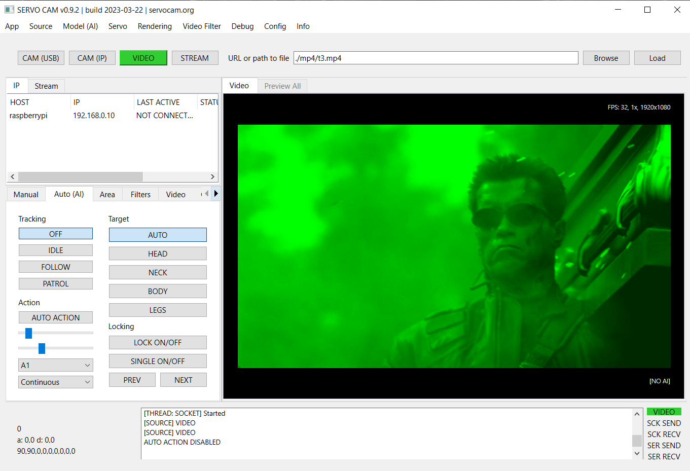
Auto Mode (Artificial Intelligence - AI)
The mode allows for automatic control using the selected artificial intelligence (AI) model.
The design of the application allows you to implement any AI model, in the current version the following neural network models are available:
Movenet - a model for detecting human movement
Mobilenet SSD - a model for detecting and classifying objects (e.g. person, car, tank, cat, dog, etc.)
OpenCV - motion detection is done using the OpenCV library
Movenet model is available in 3 versions:
SINGLE POSE / ONE (lightning version) - allows you to track only one person at a time
SINGLE POSE / ONE (thunder version) - as above, but works with greater accuracy at the expense of more computing power required
MULTI POSE / MANY (lightning version) - allows you to track many people at once
The appropriate AI model can be selected from the Model (AI) menu.
Note: for the automatic mode to be active, it is required to select a model from the list.
Auto mode tab view:

Auto modes (tracking)
OFF - automatic control off
IDLE - tracking on the screen is enabled, however, no actions such as servo movement are performed
FOLLOW - enables tracking of the object, and the mechanism starts to follow the object and commands are sent to the servos
PATROL - patrol mode, when an object is detected, it works as the “FOLLOW” - while in the absence of a target, the mechanism automatically switches to patrol mode, in which the servo moves from one direction to another in the full range of movement of the mechanism in the X axis, in to find an object within the full field of view
Tracking modes
LOCK - causes automatic locking of the system on the detected object
SINGLE - to be used with LOCK option, after turning on the system tries to keep attention only on one object and not automatically switch to other objects, e.g. after performing an action
Switching the object to lock (arrows at the bottom)
« - locates the system on the previous object in the X axis (if the selected AI model allows you to track many objects at once)
» - locates the system on the next object in the X axis (if the selected AI model allows you to track many objects at once)
Action modes
Similarly to the manual mode, you can select the mode of activation of the action (SINGLE, CONTINUOUS, etc.), with the difference that in the AUTO mode, the activation of a given action takes place automatically after the system locks itself on the object.
“Action duration” slider - allows you to decrease or increase the duration for continuous actions, zero value (0) causes no disablement.
Slider “time to switch to the next object” - allows you to decrease or increase the time between switching to the next object.
AUTO ON/OFF action - enables automatic switching on of the action selected from the list.
If the AUTO ON/OFF action switch is turned on, the action selected from the list is automatically activated after the system locks onto the object. After the time has elapsed (if SINGLE mode is not enabled, the system tries to switch to the next detected object and the procedure is repeated. The times between switching between objects and the duration of the action can be modified using the sliders.
Target
This option applies only to “person” objects and the Movenet model.
AUTO - causes the system to be located at the most optimal point on the person’s body
HEAD - causes the system to be placed on the head
NECK - causes the system to be placed on the neck
BOD - causes the system to be located on the body / center of gravity
LEGS - causes the system to locate itself on the legs if they are available in the field of view
Remote Status
The software allows for communication from the client to the server -
this allows you to read the status from a remote device and transfer it
to the server (on an ongoing basis or at intervals), thus informing, for
example, about the status of the device after performing a given action
on it. This status appears on the screen in the lower left corner of
the screen with the image from the camera and on the list of
clients in the case of a remote connection. You can specify what
status data are to be sent back to the server - more about this in the
chapter on preparing your own device status. Status polling can be
enabled or disabled in the client application with the --status
argument:
./client.py --status=1
Restriction Areas
With this tool, you can limit the areas for action for:
Tracking - object detection
Patrol - patrol mode
Action - automatic action triggering
After defining (drawing with the mouse) a boundary area on the video image, the specified operation will be limited to this area only.
The following options are available in the tool:
ON/OFF - enables or disables the use of a given area
Select – enables drawing a new area with the mouse
Clear - removes the current active area
World - enables or disables the mapping of the area to the real world (if enabled, the area will be assigned to coordinates in real space, not to the screen, i.e. the area will “virtually” follow the movement of the mechanism by sticking to a point in real space)

You can also enter coordinates manually using the fields at the bottom.
It should be remembered that they must be given in a normalized form (as floating-point numbers between 0-1 range, where 0 = the beginning of the coordinate system and 1 = the end of the coordinate system). When manually edit, then X, Y and width and height values needs to be defined.
Limiting filters
In this tab, you can specify filters for the behavior during automatic control.
Here you can specify the classes of objects to which the operation will be limited, e.g. person,car (without spaces) and the minimum required score.
You can specify constraints for several different types of events:
Detect - the condition will be applied at the stage of object detection
Tracking - the condition will be applied at the stage of starting tracking
Action - the condition will be applied when activating the action
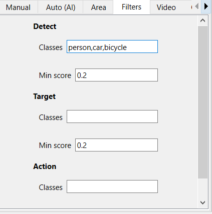
Note: Please note that not every AI model can classify objects, there is only one model in the package: Mobilenet. The Movenet model does not allow for classification, it is adapted only to the detection of human movement and each object detected by it will have the “person” class.
Options
In this tab you can configure basic parameters such as tracking speed, servo response and other parameters. There are basic options here, more options are in the configuration file.
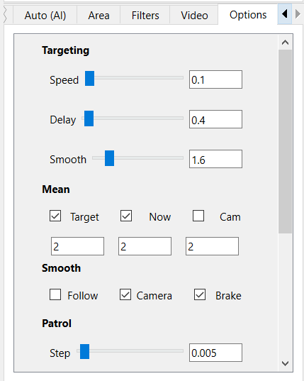
Targeting
Speed - the speed at which the crosshair follows the target object
Delay - delay in the execution of the next step after the target object
Smooth - The distance at which the tracking of the target slows down when approaching the object
By setting different combinations of the above options, you can get different effects depending on your needs.
Mean
Target - enables calculation of the average position for the point of the target object (smooths to previous values)
Now - enables calculation of the average position for the tracking point (smooths to previous values)
Cam - enables calculation of the average position for the camera point (smooths to previous values)
The numerical inputs below determine how many previous values the algorithm should take into account when averaging positions.
Smooth
Follow - smoothes the tracking motion
Camera - smoothes camera movement
Brake - causes the servo to be deactivated in the absence of a target object
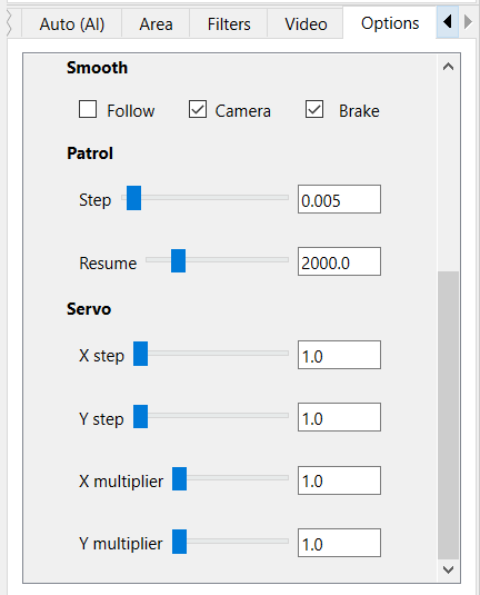
Patrol
Step - the distance to be covered in one step (the larger the faster the servo)
Resume – the time in ms after which the patrol mode is to be resumed after the loss of the tracked object
Serwo / Servo
X / Y step - every difference in position (in angles) the update of the servo position should take place (sending a command to the servo)
X / Y multiplier - angle multiplier, allows you to multiply the angle by which the movement is made (the nominal value is multiplied by the multiplier)
Video Filters
From the menu level, you can enable filters for the video.
Several predefined filters are available, such as digital simulation of night vision or thermal imaging.
Each of the filters can be enabled for both video input and video output.
Input filters are applied before the video enters the neural network (AI receives the filtered video already), output filters are applied only for the video already displayed on the output to the user. You can enable as many filters as you want at once.
An example of the effect after enabling Nightvision filter, which digitally enhances the video:
Configuration
“config.ini” file
When the application starts, the entire configuration is loaded from the config.ini file located in the user home dir directory. The file is copied from app directory to the user’s home directory in the system at first launch and then is readed from there. By modifying this file (in your home dir), you can change the startup parameters of the application.
The file can be edited directly from the application - in the Configuration > Edit startup config.ini menu option.
The configuration file allows for full configuration of the whole, e.g. the language of the server application can be changed in the config.ini file using the app.lang parameter (2 languages are available: en and pl):
# config.ini

app.lang = en
The localization texts are in the files in the locale directory in the directory with the application.
Tip: in case of an incorrect configuration, you can load back the default configuration file using the Load defaults and then save the changes . You can also copy the default file from the assets/defaults/config.ini directory and replace the modified config.ini file.
A similar configuration for the web application is in the “config.js” file.
A full description of all parameters in the configuration file can be found later in the documentation.
“hosts.txt” file
When the application starts, the list of clients is loaded from the hosts.txt file located in the user home directory. The file is copied from app directory to the user’s home directory in the system at first launch and then is readed from there. By modifying this file (in your home dir), you can set your own list of clients list loaded by default in the application.
The file can be edited directly from the application, in the Configuration > Edit hosts.txt menu option.
“streams.txt” file
When the application starts, the list of hosts with streams is loaded from the streams.txt file located in the user home directory. The file is copied from app directory to the user’s home directory in the system at first launch and then is readed from there. By modifying this file (in your home dir), you can set your own list of hosts list loaded by default in the application.
The file can be edited directly from the application, in the Configuration > Edit streams.txt menu option.
Client - client application (Python, Raspberry, PC, Arduino)
The client application is designed to receive commands from the server application and physically communicate with the camera and servos. It allows for remote control using a server application connected to it. It is located in the Client directory . A Python version is prepared for any system such as Windows, Linux or Rasbian in Raspberry, as well as a code to be uploaded to Arduino. The application can be run on any device equipped with a Python interpreter.
It can be run on any PC, as well as a Raspberry minicomputer. After running on the computer, it starts listening for connections from the server and, if the connection is established, it starts sending the image from the connected camera via the network/WiFi to the server application. At this time, the server application can transfer commands to control the mechanism to the client application, which the client application sends further to the hardware (Arduino or directly from the Raspberry, depending on how the whole and selected components are connected).
Client installation on Raspberry Pi (Python >= 3.9 required):
python -m venv ./venv
source ./venv/bin/activate
pip install -r requirements-pi.txt
Client installation on PC (Python >= 3.9 required):
python -m venv ./venv
source ./venv/bin/activate
pip install -r requirements.txt
Note: Before installing from “requirements.txt”, you may need to install the packages first:
pip install --upgrade pip setuptools wheel
sudo apt-get install build-essential cmake pkg-config libjpeg-dev
libtiff5-dev libjasper-dev libpng-dev libavcodec-dev libavformat-dev
libswscale-dev libv4l-dev libxvidcore-dev libx264-dev
libfontconfig1-dev libcairo2-dev libgdk-pixbuf2.0-dev libpango1.0-dev
libgtk2.0-dev libgtk-3-dev libatlas-base-dev gfortran libhdf5-dev
libhdf5-serial-dev libhdf5-103 python3-pyqt5 python3-dev -y
Note: the installation of OpenCV on the Raspberry may take some time (the system may be unresponsive for a long time).
The application can be launched in one of two modes: standard (desktop) and web:
python ./client.py
python ./client.py --web=1
In standard (desktop) mode, it enables connection to a desktop server application, and in web mode, it allows connection to a remote web application (via a browser). Both of these modes in the current version cannot work simultaneously.
The application can be launched with arguments, the startup parameters can be modified in the config.ini file located in the directory with the application.
The type of connected hardware (Arduino or Raspberry) can be defined in the config.ini file using the client.device option:
# config.ini

client.device = arduino
or
# config.ini

client.device = raspberry
The device type can also be selected when starting the application,
using the --device parameter e.g.:
python ./client.py --device=arduino
python ./client.py --device=raspberry
Note: if the client application is running on a Raspberry, but an Arduino is additionally connected to the Raspberry to control the mechanisms, set device = arduino (and not raspberry) here. We set the raspberry device only when we want to control it directly using raspberry GPIO pins.
It is possible to specify here raspberry as a device also in the case of control using Arduino, but in this case, in its configuration, specify the serial port for the connected Arduino and select serial instead of gpio as the output:
# config.ini

client.device.raspberry.serial.output = /dev/ttyUSB0
client.device.raspberry.mode.output = serial
Tip: On Linux/Raspberry systems, Arduino will usually be available on ports: /dev/ttyUSB0 (nano) or /dev/ttyACM0 (uno)
USB connection
If the Raspberry will be connected via the USB port to the control computer (server), and not via WiFi, then in the configuration, enter the input as serial instead of network and specify the serial port used for transmission from the computer:
# config.ini

client.device.raspberry.serial.input = /dev/ttyS0
client.device.raspberry.mode.input = serial
For greater reliability, the application should be run in conjunction with supervisory software such as Supervisor, which monitors the status of running applications on an ongoing basis and can, for example, restart them if necessary.
You can run the client application with the following arguments:
python ./client.py --argument1=value1 --argument2=value2 …
Tip: -short option –option - description (default)
-c –camera - camera index/number (0)
-d –device – type of connected device (raspberry or arduino)
-p –pi - on/off using Raspberry Pi camera (0)
-x –width - width of the captured image /px/ (1280)
-y –height - height of captured image /px/ (720)
-i –ip - client IP address (0.0.0.0)
-s –server-ip - Default server IP
-w –web - on/off image streaming to browser mode (MJPEG) (0)
-v –verbose - on/off displaying the status in the terminal (0)
-n –hidden - on/off silent mode, without any messages, statuses and etc. in terminal (0)
-u –status - on/off check device status and send to server (0)
-e –debug - on/off debug mode (0)
If no arguments are given during startup, the default values read from the config.ini configuration file are used.
In the case of the client for Linux, bash scripts are prepared to run
the application, which make it easier to run, they are located in the
./bin directory:
start – a script that starts the client in remote mode (to operate with desktop application), in silent mode
start-web – a script that starts the client in web mode (mode that allows you to connect via webbrowser), in silent mode
It is recommended to run the client in a virtual environment (e.g. using python venv):
python -m venv ./venv
source ./venv/bin/activate
pip install -r requirements.txt
Scripts from ./bin directory run the client in a virtual environment. After modifying the paths, they can be used as launch shortcuts (after creating the venv environment as above). In the package, in the “examples/supervisor” directory there are also sample configuration files for the supervisor, which can be placed in your configuration directory: /etc/supervisor/conf.d.
Sample supervisor configuration file:
# /etc/supervisor/conf.d/client.conf

[program:client]
command=/home/pi/client/bin/start
directory=/home/pi/client/bin
autostart=true
autorestart=true
user=pi
After adding the configuration file, give it the appropriate permissions and reload the configuration:
sudo chmod 0770 client.conf
sudo chown root:pi client.conf
sudo supervisorctl reload
sudo supervisor restart all
Where pi is an example username. It is also worth activating the supervisor service so that it is started automatically when the system starts:
sudo service supervisor enable
Such configuration will automatically start the supervisor during device startup, then autostart the client and supervise it with the help of the supervisor, who from now on will always watch if the client is still running and will restart it in case of any problems.
For more informations about using Supervisor, please visit: https://supervisord.org
Below is a description of the client configuration options found in the config.ini file located in the root directory of the client application:
# config.ini
security.web.token - security token for web applications, string
security.aes.video - on/off video data encryption using AES during connection, bool [1|0] (1)
security.aes.data - on/off data encryption with AES during connection, bool [1|0] (1)
security.aes.key - 16-character secret encryption key, must be the same on the client and on the server, string
log.info.enabled - on/off logging info to file, bool [1|0] 0
log.info.file - log file, string (info.log)
log.error.enabled - on/off log errors to file, bool [1|0] 1
log.error.file - error log file, string (error.log)
client.ip - client socket IP, string (0.0.0.0)
client.hostname - custom hostname, string
client.device - type of connected device [raspberry|arduino], string (arduino)
client.port.data - port for data and command transmission, integer (6666)
client.port.conn - connection initiation port, integer (6667)
client.port.status - port for receiving status from the device, integer (6668)
client.port.web - port for video streaming in the webserver option, integer (8888)
client.port.video - port for video streaming in desktop option, integer (5555)
client.socket.pull.wait - receiving socket wait option, bool [1|0] (0)
client.socket.pull.linger - receiving socket linger option, bool [1|0] (0)
client.socket.push.wait - sending socket wait option, bool [1|0] (0)
client.socket.push.linger - push socket linger option, bool [1|0] (1)
client.web - on/off video stream for web application, bool [1|0] (0)
client.server.ip - IP address of the default server, string
client.camera.idx - default camera idx, integer (0)
client.camera.use_pi - on/off Raspberry Pi camera (CSI), bool [1|0] (0)
client.camera.width - width of the captured video in px, integer
client.camera.height - height of the captured video in px, integer
client.verbose - on/off displaying status messages in the console, bool [1|0] (0)
client.debug - on/off displaying debug messages in the console, bool [1|0] (0)
client.silent - on/off silent mode, disables console output, bool [1|0] (0)
client.status.check - on/off querying device status, bool [1|0] (0)
client.status.interval - second interval for querying the device status, integer (3)
client.stream.jpeg - on/off video compression during streaming, bool [1|0] (0)
client.stream.jpeg.quality - defines JPEG compression ratio when enabled, integer (85)
client.stream.resize - on/off scaling the video during streaming, specify the width in px, or leave it empty, int
client.device.arduino.serial - serial (input) port for PC/Raspberry connection, string (/dev/ttyUSB0)
client.device.arduino.data_format - format of data sent to the device, JSON or RAW, string (RAW)
client.device.raspberry.serial.input - serial (input) port for connecting to the server, string (/dev/ttyS0)
client.device.raspberry.serial.output - serial (output) port for connection to the device, e.g. Arduino, string (/dev/ttyUSB0)
client.device.raspberry.mode.input - input connection mode, network or serial, string [network|serial] (network)
client.device.raspberry.mode.output - device control mode, via built-in GPIO, or using an Arduino connected via a serial port, string [gpio|serial] (serial)
client.device.raspberry.data_format - format of data sent to the device, JSON or RAW, string (RAW)
client.device.raspberry.pin.servo_x - pin for X servo, board address, integer (32)
client.device.raspberry.pin.servo_y - pin for servo Y, address on the board, (33)
client.device.raspberry.pin.action_A1 - pin for action #1, address on the board, (16)
client.device.raspberry.pin.action_A2 - pin for action #2 address on the board, (18)
client.device.raspberry.pin.action_A3 - pin for action #3 address on the board, (22)
client.device.raspberry.pin.action_B4 - pin for action #4, address on the board, (24)
client.device.raspberry.pin.action_B5 - pin for action #5, address on the board, (26)
client.device.raspberry.pin.action_B6 - pin for action #6, address on the board, (36)
serial.baud_rate - serial port baud rate, integer (9600)
serial.data.format - sent data format, string [JSON|RAW] (RAW)
servo.use_limit - on/off movement mapping according to the limit value, instead of max angle, bool [1|0] (0)
servo.angle.start.x - initial deflection angle of the servo in the X axis, integer (90)
servo.angle.start.y - initial deflection angle of the servo in the Y axis, integer (90)
servo.angle.min.x - min. deflection angle of the servo in the X axis, integer (0) # servo parameter
servo.angle.min.y - min. deflection angle of the servo in the Y axis, integer (0) # servo parameter
servo.angle.max.x - max. deflection angle of the servo in the X axis, integer (180) # servo parameter
servo.angle.max.y - max. deflection angle of the servo in the Y axis, integer (180) # servo parameter
servo.limit.min.x - min. allowed servo movement in X axis, integer (0) # physical, real possibility
servo.limit.min.y - min. allowed servo movement in Y axis, integer (0) # physical, real possibility
servo.limit.max.x - max. allowed servo movement in X axis, integer (180) # physical, real possibility
servo.limit.max.y - max. allowed servo movement in Y axis, integer (180) # physical, real possibility
servo.freq.x - X-axis pulse frequency in Hz, integer (50)
servo.freq.y - Y-axis pulse frequency in Hz, integer (50)
servo.delay.x - delay in milliseconds after moving the X axis, float (0.02)
servo.delay.y - delay in milliseconds after moving the Y axis, float (0.02)
servo.cycle.start.x - starting value for the “duty cycle” in the X axis, float (0)
servo.cycle.start.y - starting value for “duty cycle” in Y axis, float (0)
servo.cycle.min.x - min. value for “duty cycle” in X axis, float (2.5)
servo.cycle.min.y - min. value for “duty cycle” in Y axis, float (2.5)
servo.cycle.max.x - max. value for “duty cycle” in the X axis, float (12.5)
servo.cycle.max.y - max. value for “duty cycle” in Y axis, float (12.5)
servo.angle.step.x - min. required difference in degrees to send command in X-axis, integer (1)
servo.angle.step.y - min. required difference in degrees to send command in Y axis, integer (1)
servo.angle.multiplier.x - multiplier of steps in X axis, integer (1)
servo.angle.multiplier.y - multiplier of steps in the Y axis, integer (1)
Tip: on Raspberry (older models, such as 3A, it is recommended to increase the size of the swap file to at least 1GB):
sudo dphys-swapfile swapoff
sudo nano /etc/dphys-swapfile
# /etc/dphys-swapfile

CONF_SWAPSIZE=1024 # <------------ 1 GB
sudo dphys-swapfile setup
sudo dphys-swapfile swapon
sudo raspi-config
and then in the raspi-config expand the filesystem to the entire SD card.
Web application (web browser)
The web application is in the Web directory. This version of the application runs under the user’s browser.
The browser should have GPU support”, Google Chrome is recommended for best performance. To run the web application, you must first run a **webserver on your computer - it can be any web server, such as Nginx or Apache, it can also be a simple development server available from Python. In the package, in the Web directory, there is a simple python framework/webserver - Flask, you can run it with:
pip install -r requirements.txt
python ./start.py
After starting, the webserver will be started and the web application
will start automatically on port 8000, at the address:
http://localhost:8000 - the number of port can be
changed with the --port parameter , e.g.:
python ./start.py --port=9999
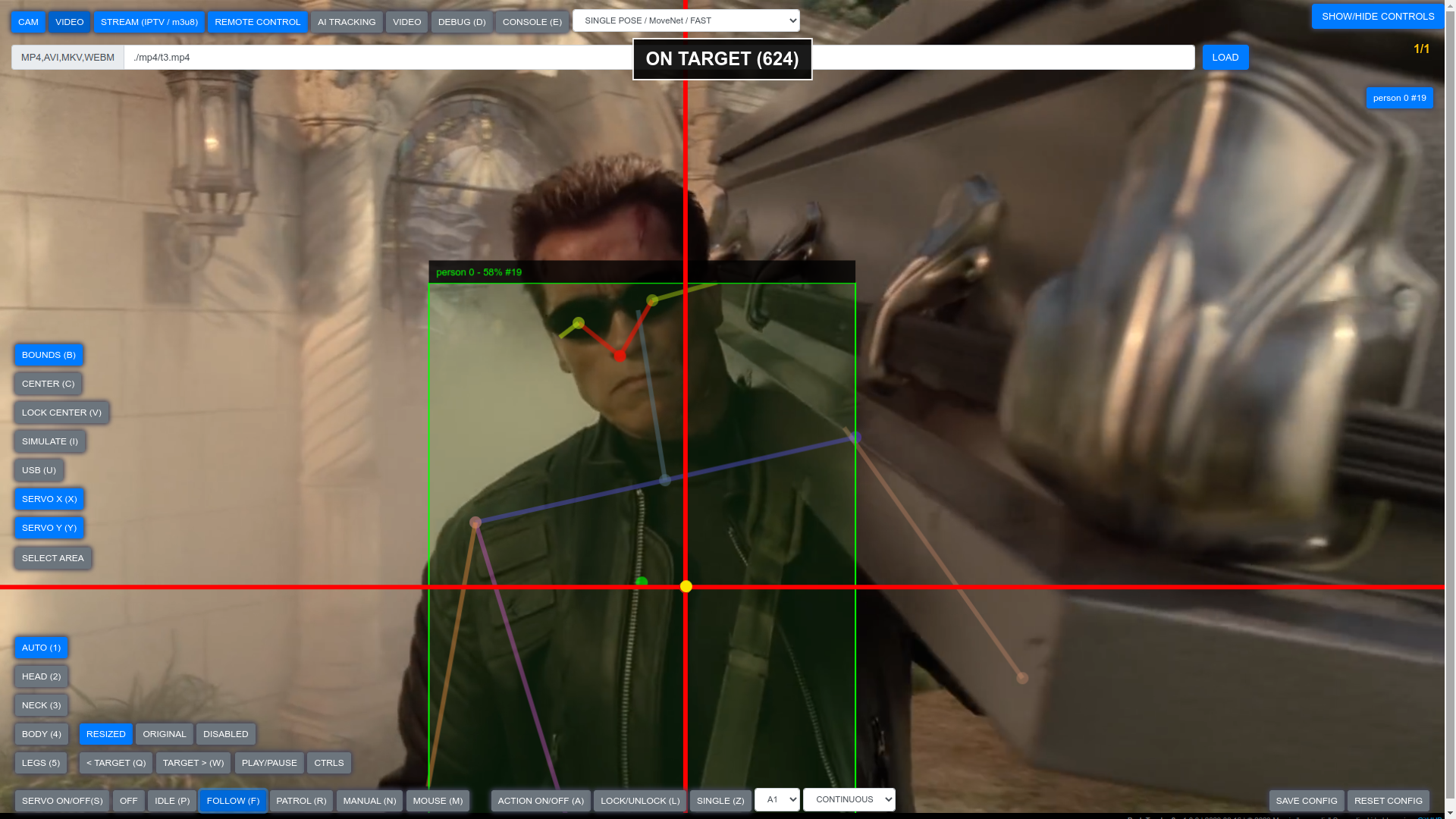
The interface of the web application differs from the desktop application, however, the operating modes and settings are similar to those in the desktop application.
Modes of operation
The connection mode with the remote client (REMOTE option at the
top of the screen) differs from the corresponding mode in the desktop
application. To enable the connection in the web application, you need
to run the client with the --web parameter:
python ./client.py --web=1
This causes sharing of the image from the camera as an MJPEG and serving it via the Flask framework, which then can be read by the browser. The image is then made available at the IP address of the device, e.g.:
http://192.168.0.15:8888
Port 8888 can be changed in the client’s config.ini file:
# config.ini

client.port.web = 8888
In the current version, the client application can be run either in web mode or in default mode (IP sockets), it is not possible to run both modes at the same time.
Note: remember to properly configure the access token in the config.js
file if encryption/securing of data or access is enabled (more about this
in the Security section).
Access to the device from the public network
The software and hardware in their standard configuration work only in the local network.
If there is a need to connect to the device via a public network (internet), traffic to the device must be redirected. To do this, redirect the ports on the router and unblock the ports used for communication by the client software on the firewall. The configuration of the router may differ depending on the router you have, but the whole thing boils down to redirecting the following ports on the router from the external network to the client device, which are opened on the client:
port 6666 - this is the socket receiving control commands from the server - ZMQ / PULL
port 6667 - this is a temporary socket used to initiate the connection - TCP / STREAM
and possibly:
port 8888 - video stream in MJPEG format for WWW and receiving commands from the browser in the case of a running web client, or working in STREAM mode - HTTP mode
The following ports are opened (binded) on the server side:
5555 - for video transmission from the client to the server - ZMQ
6668 - for receiving status/data from the client - ZMQ / PULL
The client ports must be forwarded from the router to the device with the client application, e.g. to the IP address of the Raspberry computer, if the client is a Raspberry. After redirecting the ports to the device, you will be able to connect from the public network by specifying the IP address of the router.
The numbers of the ports can be changed in the config.ini file. Their default numbers are given below:
# config.ini

client.port.data = 6666
client.port.conn = 6667
client.port.status = 6668
client.port.web = 8888
client.port.video = 5555
Security - connection encryption
Data sent over the public network should be encrypted.
This is not critical on a trusted local network, but when transferring over a public network, you should secure the data being sent over the network. The software has implemented the ability to encrypt the video image transmitted over the network. To enable image encryption for remote connections when sending an image to a desktop application, enable the security.aes.video option in config.ini file:
security.aes.video = 1
The above parameter enables video encryption for remote mode (desktop application).
Using a separate parameter, you can also enable encryption of the transmitted control data (sent via network sockets). To enable encryption of such data as well, enable the security.aes.data option:
security.aes.data = 1
If encryption is enabled, you must also provide any random, 16-character key with which data will be encrypted using the AES cryptographic algorithm:
security.aes.key = abcdef1234567890
Securing traffic for a web application is different - it requires specifying a special token that will be required to connect to the webserver. This token should be as random as possible, it is best to use some generator available online to generate a maximum random string of characters, e.g. you can use: https://generate-random.org/api-token-generator
The token must then be specified in the config.ini file:
security.web.token = abcdef1234567890
To connect to a client that has token-secured access, the token must be attached to the address using the ?token= parameter:
E.g.:
http://192.168.0.15:8888/?token=abcdef1234567890
If the token is defined and is not provided in the address, or an incorrect token is provided, the connection will be rejected (HTTP code 403 Forbidden).
Note: if you set the access token in the web option, you should
also configure it in the web application - this should be done in the
config.js configuration file located in the directory with the web
application, in the option security > webToken:
// config.js

security: {
   webToken: 'xxxxxxxxxxx',
},
Note: Encrypting data may slow down your connection slightly, introduce latency, and cause higher CPU usage, especially on low-end devices like the Raspberry.
When connecting over a public network, it is also worth considering additional measures, such as Wireguard, HTTPS encrypted connection, or IP tunneling.
Device status - reading from sensors, sending status to the server
Using the client, you can prepare your own device status, which will then be sent remotely to the server application. Thanks to this, you can have remote access to the state of the machine (e.g. readings from sensors) at all time. Own status can be defined both in the Python version for Raspberry and PC, as well as in the version for Arduino.
Raspberry and PC
The client version for Raspberry and PC has a python class Status in the client’s main directory.
It is defined in the status.py file and contains two methods for your own use:
def init(self)
def get_status(self)
In the first method - init(), you can define actions launched during
device startup, such as setting the appropriate pins for sensors or
other required startup procedures. The method is called at client
startup, after GPIO.setmode(GPIO.BOARD) has been initialized.
Example of use:
# status.py

import RPi.GPIO as GPIO

class Status:
   def __init__(self, worker=None):
      self.worker = worker

   def init(self):
      GPIO.setup(38, GPIO.IN)
In the second method - get_status() , a string with the device
status is returned, any string can be prepared here, containing, for
example, the current time or sensor readings.
Example of use:
# status.py

from datetime import datetime

class Status:
   def __init__(self, worker=None):\
      self.worker = worker

   def get_status(self):
      status = "TIME: " + datetime.now().strftime("%H:%M:%S")
      status+= ", SENSOR: " + str(GPIO.input(38))
      return status
In the class you also have access to the status of the device sent via the serial port (if, for example, the device is connected via Arduino). To access this status, just read the string value:
self.worker.serial_status
e.g.
def get_status(self):
   status = "TIME: " + datetime.now().strftime("%H:%M:%S")
   status+= ", SENSOR: " + str(GPIO.input(38))
   status+= ", STATUS FROM ARDUINO: " + str(self.worker.serial_status)
   return status
Arduino
In Arduino, sending your status can be defined in the client code, which is uploaded to the board. The code is in the Client / Arduino directory, it’s written in C++.
To add your own status, add your code to the get_status() function.
You can receive, for example, data from sensors and return it for sending to the server application.
The function must return a String object.
Example of use:
void setup() {
   // ...
}

String get_status() {
   String value = String(analogRead(0));
   String status = String(”SENSOR: ” + value));
   return status;
}

void loop() {
   // ...
}
Updating to newer versions
The current version of the software is always available for download on the project website.
When upgrading from an older version to a newer version, it is always a good idea to ensure that the version of the server software matches the version of the client software. Appropriate versions of both server and client are always in the archive with a given version. The required versions are also always listed on GitHub - for example, to check what client version the server software requires in its current version, just look at the README.md file located on GitHub in the root directory of the repository:
https://github.com/servo-cam/server
# README.md

...

Release: 0.9.3 | 2023.03.30

Requires client app: >= 0.9.2 # <----
Similarly, to check what version of server software a given client version requires, check its requirements in the repository:
https://github.com/servo-cam/client
# README.md

...

Release: 0.9.2 | 2023.03.27

Requires server app: >= 0.9.2 # <----
Updating the client software - if it is on a remote Raspberry - can be done remotely by logging into a Raspberry connected to the network, e.g. using SSH. The update usually consists only of replacing old files with new ones and restarting the running software or device. If additional steps are required (such as installing additional libraries) it will always be described in the manual.
When updating the client software, remember to modify your configuration file config.ini located in the main directory of the client. It’s best to just not overwrite the old config.ini file - if it is necessary to replace it (e.g. its format changes or additional configuration options appear) it will always be described in the manual - in any other case you can use the old one, already configured config.ini file.
Configuration files for the server application are stored in the user’s directory - updating the software to the new version of the application does not overwrite them - they are shared between different versions of the application.