Requirements and connection
Hardware
The following main components are required to build the project:
USB, HDMI or CSI camera
2x servo - one each for X and Y axes
hardware driver for servos - possible solutions: Arduino microcontroller or minicomputer in the form of Raspberry Pi/Jetson Nano or external servo driver/controller
Software
System requirements for bundled software:
Windows 10 (64bit) for Windows version (desktop)
Linux (64bit) for Linux version (desktop)
optional: web browser with GPU support for the browser version (Google Chrome recommended)
the included software supports PC (Windows, Linux), Raspberry Pi and Arduino.
No GPU is required to run the software.
In the absence of a GPU, all calculations will be done by the CPU.
Sample Components
Below is a list of components required to prepare an example construction with links to an example store (Botland):
Local connection (PC + Arduino)
Remote connection (PC + Raspberry / Arduino / WiFi)
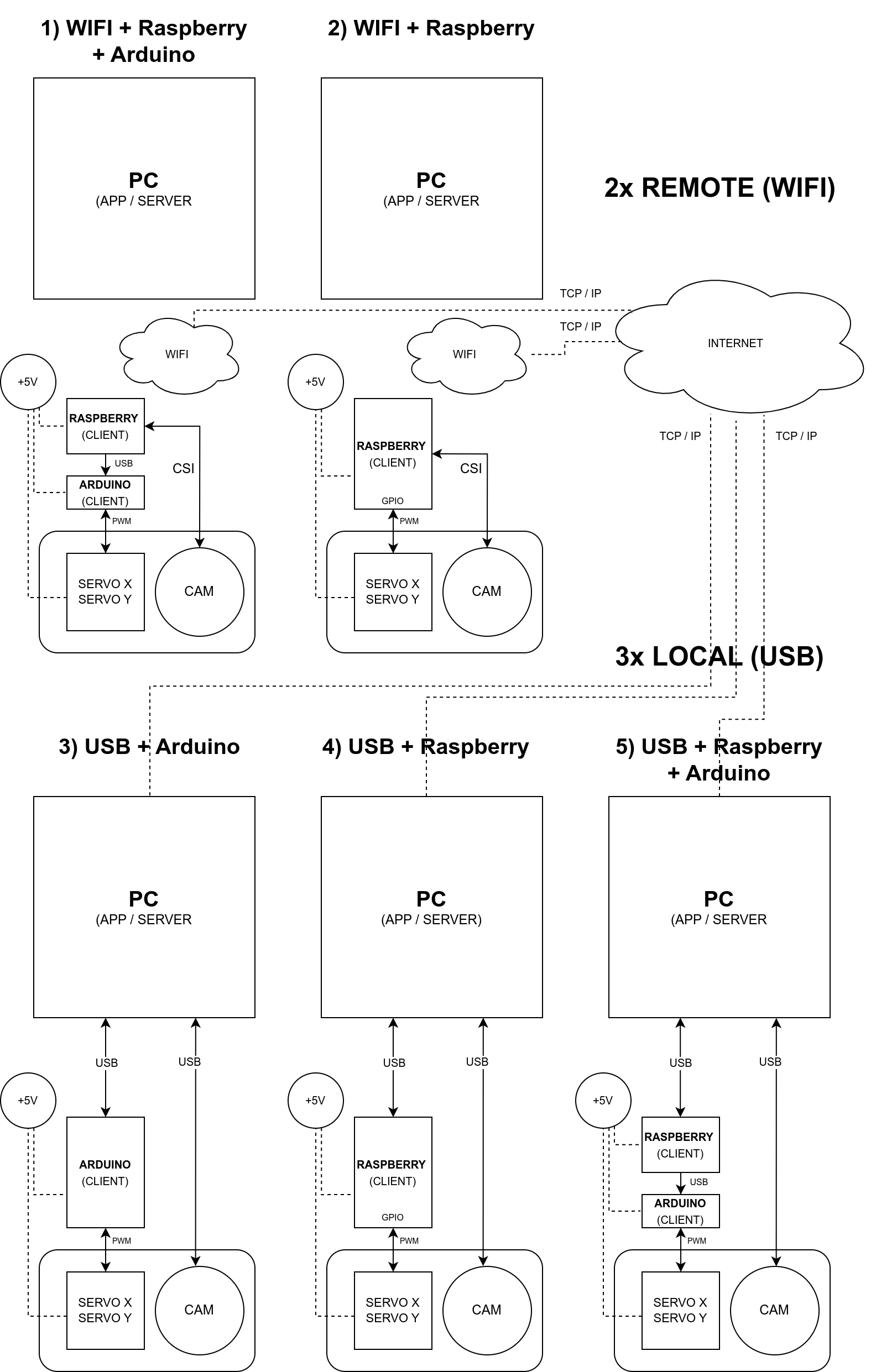
Possible connection configurations
Below is a summary diagram of all possible configurations in which all the equipment can operate in the current version. The equipment can be connected both locally and remotely.
Each of the connections has its pros and cons and its limitations - a local connection offers the lowest delays and the fastest data transfer, however, at the cost of lack of mobility, similarly, a remote connection causes minimal delays in data transfer, but allows remote control of the whole. The choice of connection method depends only on your own needs, requirements and technical capabilities. The software has been prepared to ensure operation in each of these configurations. There is also the possibility of controlling from the level of the public network (internet) - this will be described in the appropriate chapter.
The package includes prepared software for PC, Raspberry and Arduino. The software architecture and the technologies used have been selected so as to eliminate as many delays as possible and ensure the fastest possible real-time data transfer.
For remote connection, instead of the Raspberry described in the examples, any PC can be used, e.g. a Lenovo mini-computer, or any other. The software also allows for any combination of structures, i.e. in any combination, any PC, Raspberry or Arduino can be the connector with the hardware. In future releases, support for Nvidia Jetson is also planned (as a client and as a self-sufficient server due to sufficient computing power).
Note: when Raspberry is connected, servo control can be done using its built-in GPIO pins, however, a much better solution is to control servos using a microcontroller like Arduino (higher control current, less interference, greater reliability, etc.). The optimal option is, for example, connecting the Raspberry (or other computer) via Wifi, and connecting the Arduino to the Raspberry via the serial interface (USB) and then connecting the servo only to the Arduino outputs. The commands are then received via Wifi using the Raspberry and forwarded to the Arduino via USB - in this case only the Arduino deals with communication with the hardware.
All possible connection configurations are described below.
WIFI/LAN + Raspberry Pi + Arduino
In this configuration, the computer controlling the device (server) connects to the client (which can be a Raspberry or any other PC) via LAN or WLAN/WIFI. Raspberry uses Arduino connected via the USB port to control the servos using the GPIO pins of the PWM type from the Arduino microcontroller and captures video from the camera connected via the CSI connector and then sends the video to the server via the network. The control computer (server) sends servo control commands to the client over the network. To use this configuration, run on the Raspberry the client application available in the Client / PC, Raspberry directory and then on the desktop (server) application, select the remote mode CAM (IP) and then select the servo connection from Servo > Remote > (client IP address) menu. If another computer (PC) with e.g. Arduino will be used instead of Raspberry, run the client application from the Client / PC, Raspberry directory on it and select arduino as the device in client’s configuration.
Connecting pins in Raspberry (remotely) and Arduino, on the example of Raspberry Pi 3 Model A+:
The Arduino pin configuration can be changed in the C++ code included for Arduino - the code is in the Client/Arduino directory.
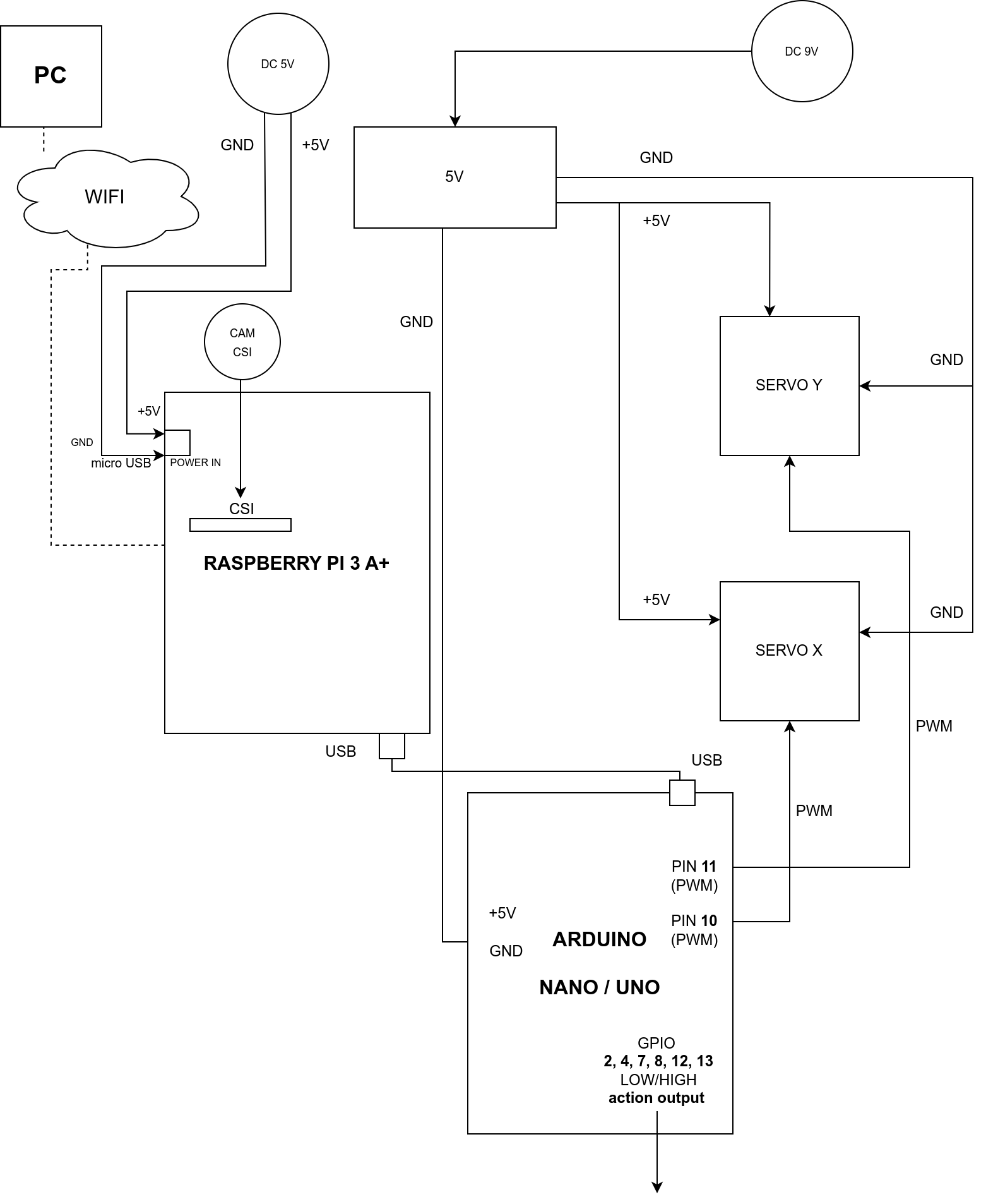
Installation procedure of the client application on Raspberry, Arduino and PC is described in more detail in a separate chapter - Software / Client.
In the next releases, an additional option is planned to connect servomotors using any hardware driver for servos.
WIFI/LAN + Raspberry Pi
In this configuration, the computer controlling the whole (server) connects to the client (which can be a Raspberry or any other PC) via LAN or WLAN/WIFI. The Raspberry, using the built-in GPIO pins of the PWM type, controls the servos and captures video from the camera connected via the CSI connector and then sends the video to the controlling computer via the network. The control computer then sends servo control commands to the client over the network. To use this configuration, run the client application available in the Client / PC, Raspberry directory on the Raspberry, and then on the desktop (server) application, select the CAM (IP) mode and then select the servo connection in Servo > Remote > (client IP address). menu. If another computer (PC) with e.g. Arduino will be used instead of Raspberry, run the client application from the Client / PC, Raspberry directory on it and select arduino as the device in client’s configuration.
Connecting pins in Raspberry (remotely), on the example of Raspberry Pi 3 Model A+:
The ground (GND) of the servo power supply must be additionally connected to the GND pin of the Raspberry in this configuration.
Note: instead of via the microUSB input (as in the diagram), the Raspberry can be connected directly to the 5V power board using the 5V and GND output pins in the Raspberry. However, this is not recommended due to the circumvention of all internals in this configuration. current protection in Raspberry.
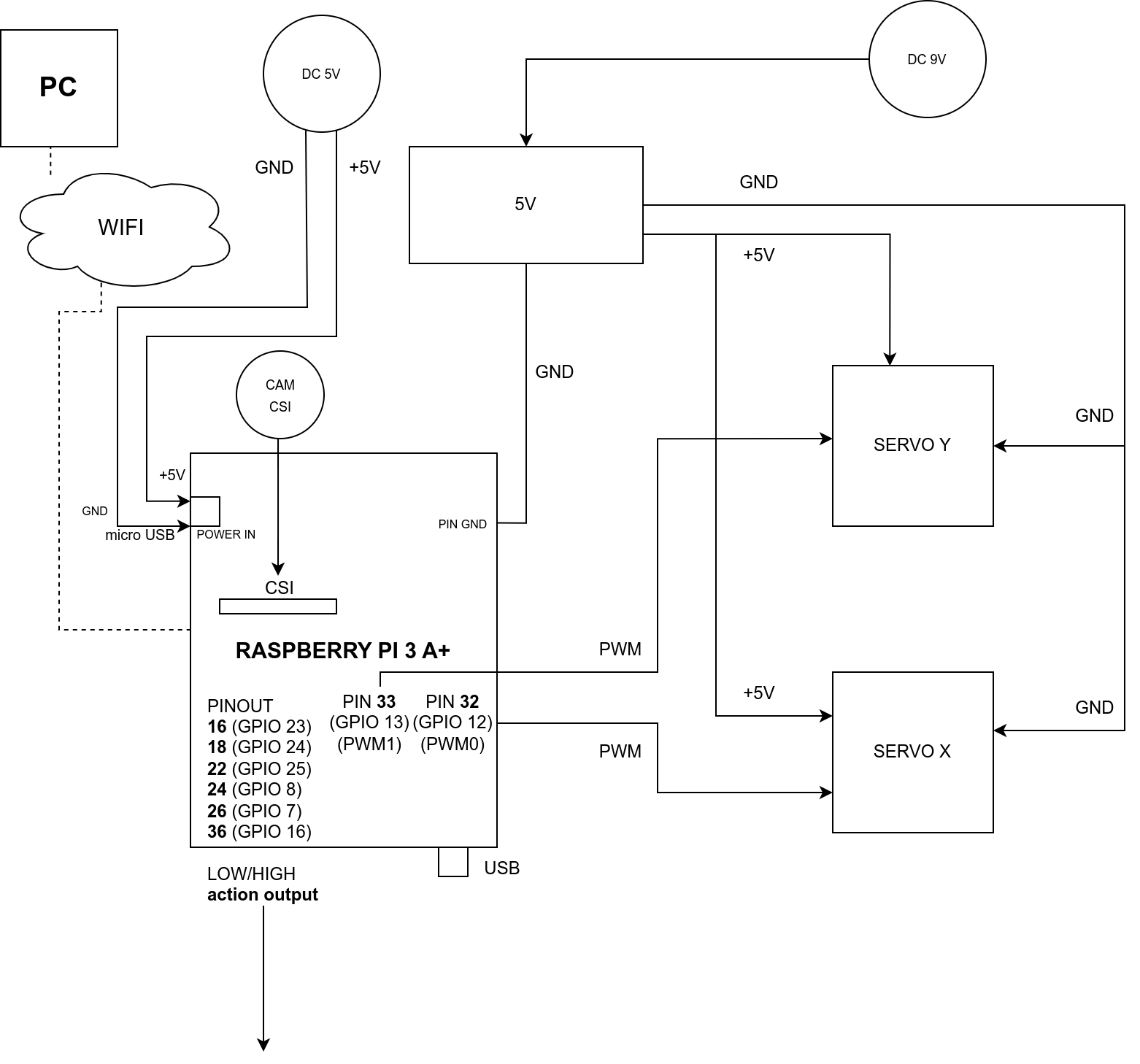
The configuration of pins for Raspberry can be changed in the config.ini file located in the directory with the client application and installed in the user’s directory in the system (pins in the configuration should be defined according to physical addresses on the board, not with GPIO names):
# config.ini
client.device.raspberry.pin.servo_x = 32
client.device.raspberry.pin.servo_y = 33
client.device.raspberry.pin.action_A1 = 16
client.device.raspberry.pin.action_A2 = 18
client.device.raspberry.pin.action_A3 = 22
client.device.raspberry.pin.action_B4 = 24
client.device.raspberry.pin.action_B5 = 26
client.device.raspberry.pin.action_B6 = 36
Installation procedure of the client application on Raspberry, Arduino and PC is described in more detail in a separate chapter - Software / Client.
In the next releases, an additional option is planned to connect servomotors using any hardware driver for servos.
USB + Arduino
In this configuration, the computer controlling the whole (server) is connected to the Arduino microcontroller via a serial port (USB). Arduino, using the built-in GPIO pins of the PWM type, controls the servos. The camera must be connected directly to the control computer via the USB port. The control software here takes care of the computational part and controls the movement of the servo motors with the connected Arduino by passing commands to it. To use this configuration, you need to upload the control code written in C++ to the Arduino (code is attached in the Client / Arduino directory), and then on the desktop (server) application, select CAM (USB) mode and then select the USB camera from the list and select the servo connection using option in the Servo > Local > (serial port address) menu.
Connecting pins in Arduino (locally), on the example of Arduino Uno / Arduino Nano:

The pin configuration can be changed in the C++ code included for Arduino - the code is in the Client / Arduino directory.
Tip: Direct, local connection of the camera and servos to a computer with a server management application (desktop) is the most reliable solution and allows for the fastest data transfer and the shortest response time. The downside of this connection is the lack of remote control, however, remote control in this configuration can be obtained by connecting via the network to the controlling computer, e.g. using VNC. Another option may be to use an active USB extension cable and use it to connect equipment located at a large distance from the controlling computer.
USB + Raspberry Pi
Note: serial connection with Raspberry requires configuration on the Raspberry side, Arduino is recommended for local connection, and Raspberry is recommended only for handling remote connections.
In this configuration, the computer controlling the whole (server) is connected to the Raspberry via a serial port (USB). The Raspberry uses the built-in GPIO pins of the PWM type to control the servos here. The camera must be connected directly to the control computer via the USB port. The control software here takes care of the computational part and controls the movement of the servo motors via the connected Raspberry by passing commands to it. To use this configuration, run the client application available in the Client / PC, Raspberry directory on the Raspberry, and then on the desktop (server) application, select the CAM (USB) operating mode and select the USB camera from the list and select the servo connection using the options in the Servo > Local > (serial port address) menu. In this configuration, any computer can be used instead of a Raspberry.
Connecting pins in Raspberry (locally), on the example of Raspberry Pi 3 Model A+:
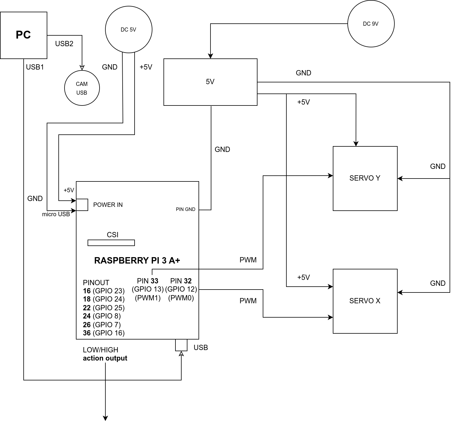
Note: instead of via the microUSB input (as in the diagram), the Raspberry can be connected directly to the 5V power board using the 5V and GND output pins in the Raspberry. However, this is not recommended due to the circumvention of all internals in this configuration. current protection in Raspberry.
The pin configuration can be changed in the config.ini file - located in the directory with the client application, this file is copied to the user’s directory during the first run and should be edited there.
USB + Raspberry Pi + Arduino
The configuration is analogous to the connection configuration via Wifi, with the only difference that the connection to the Raspberry / PC is via the USB port instead of via WiFi.